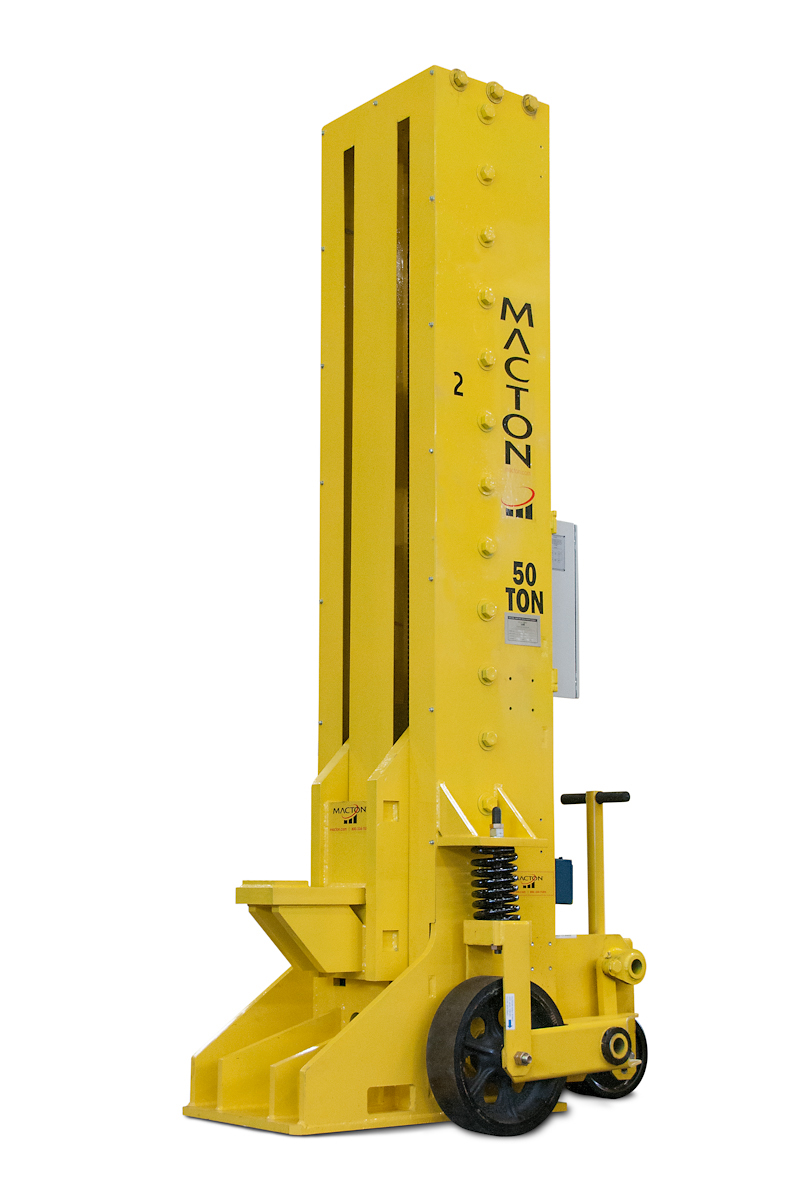
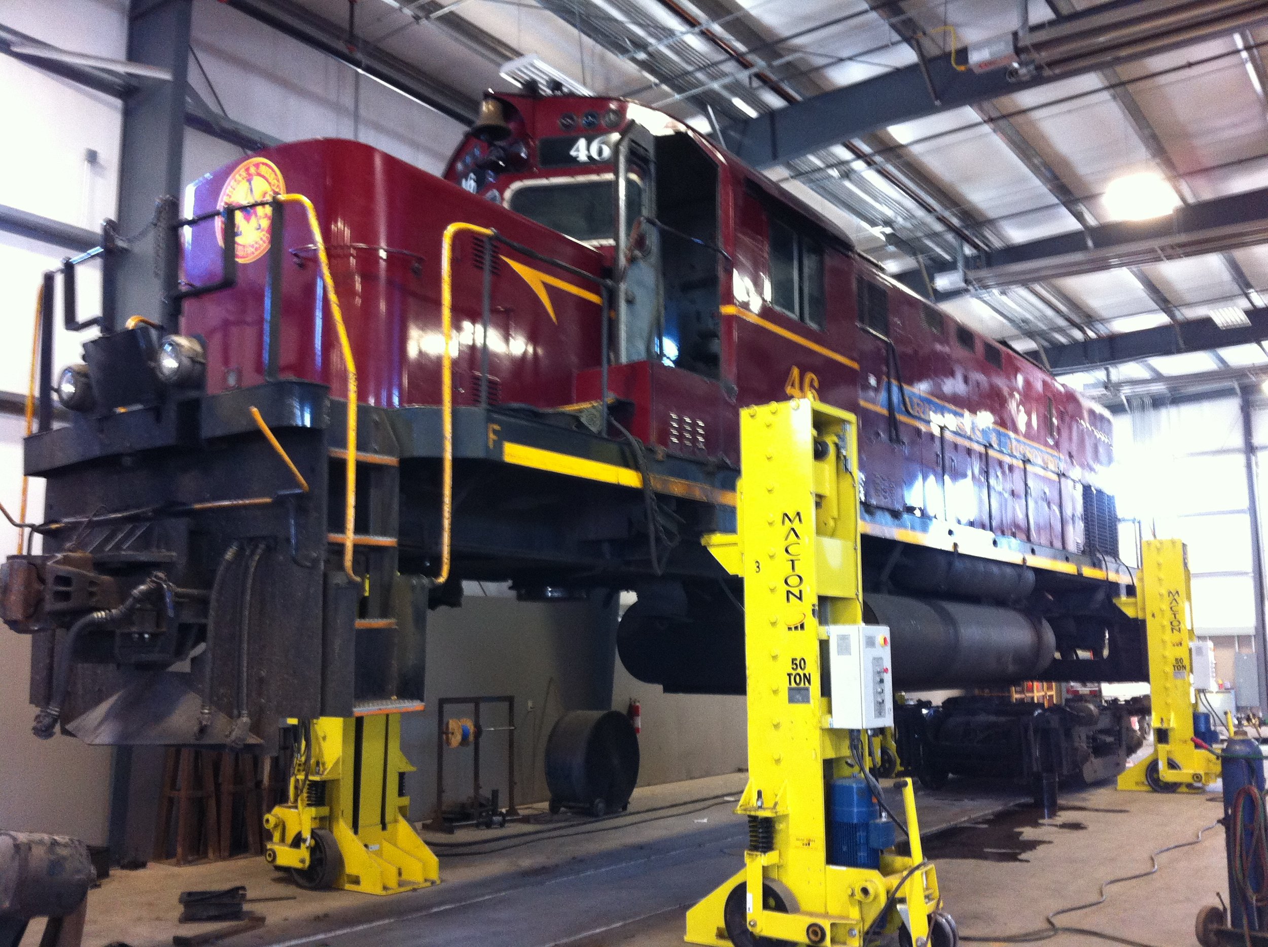
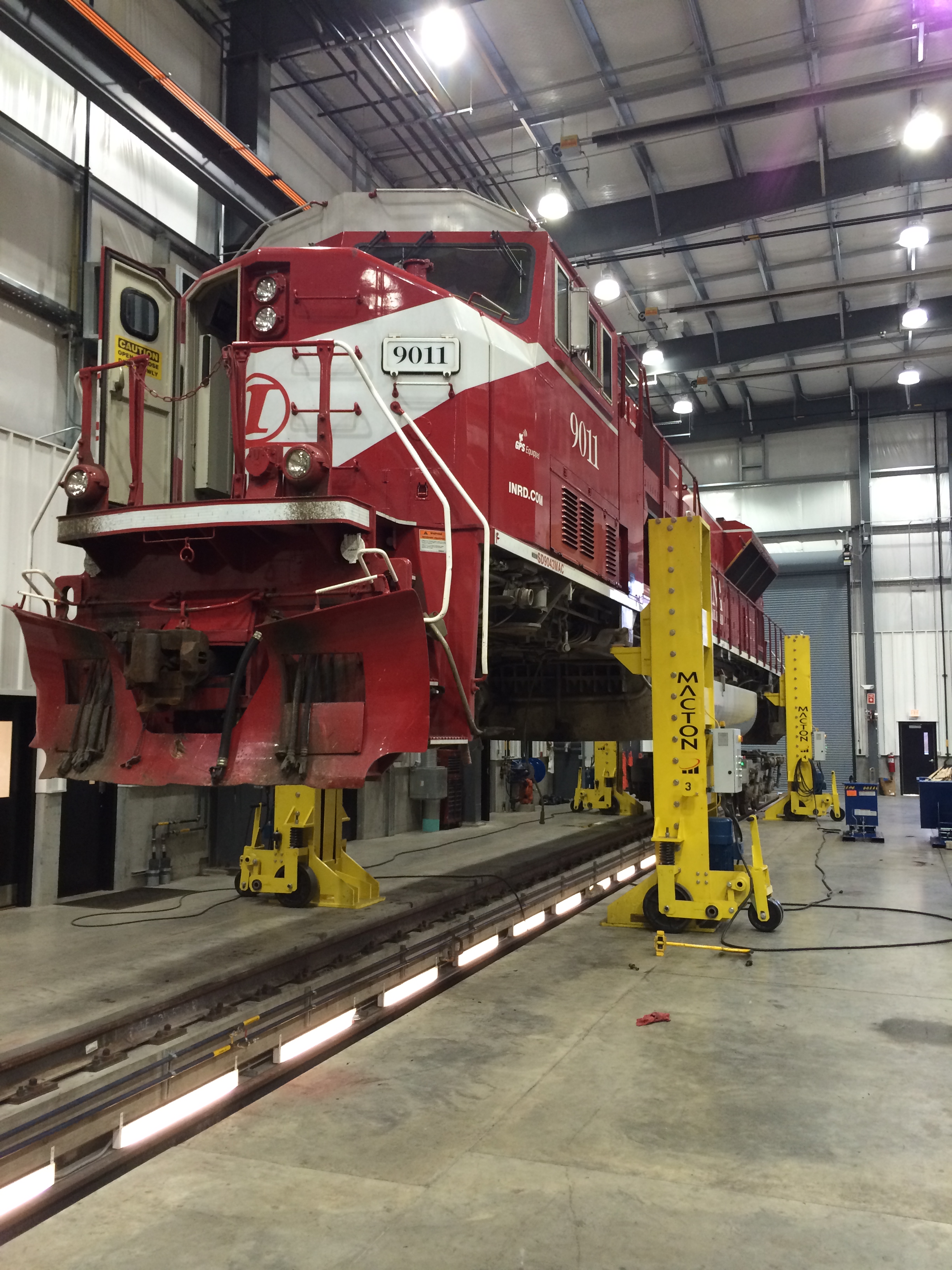
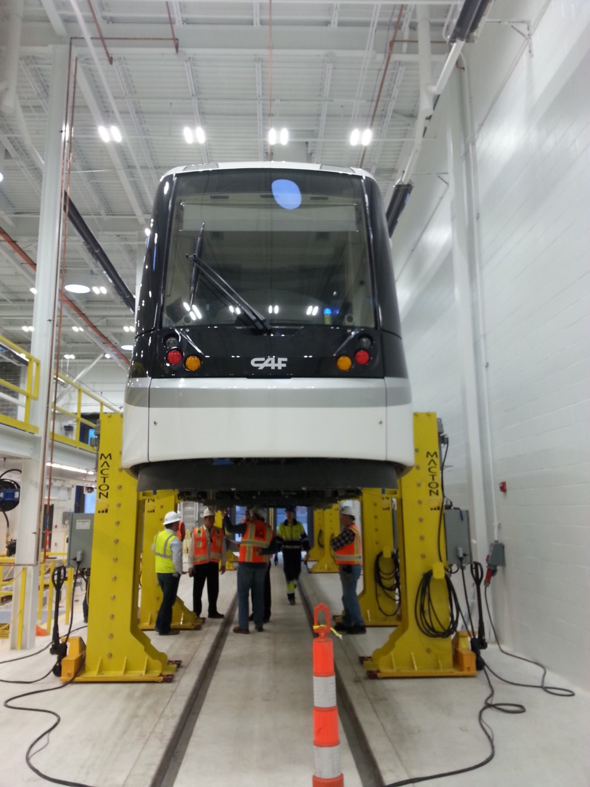
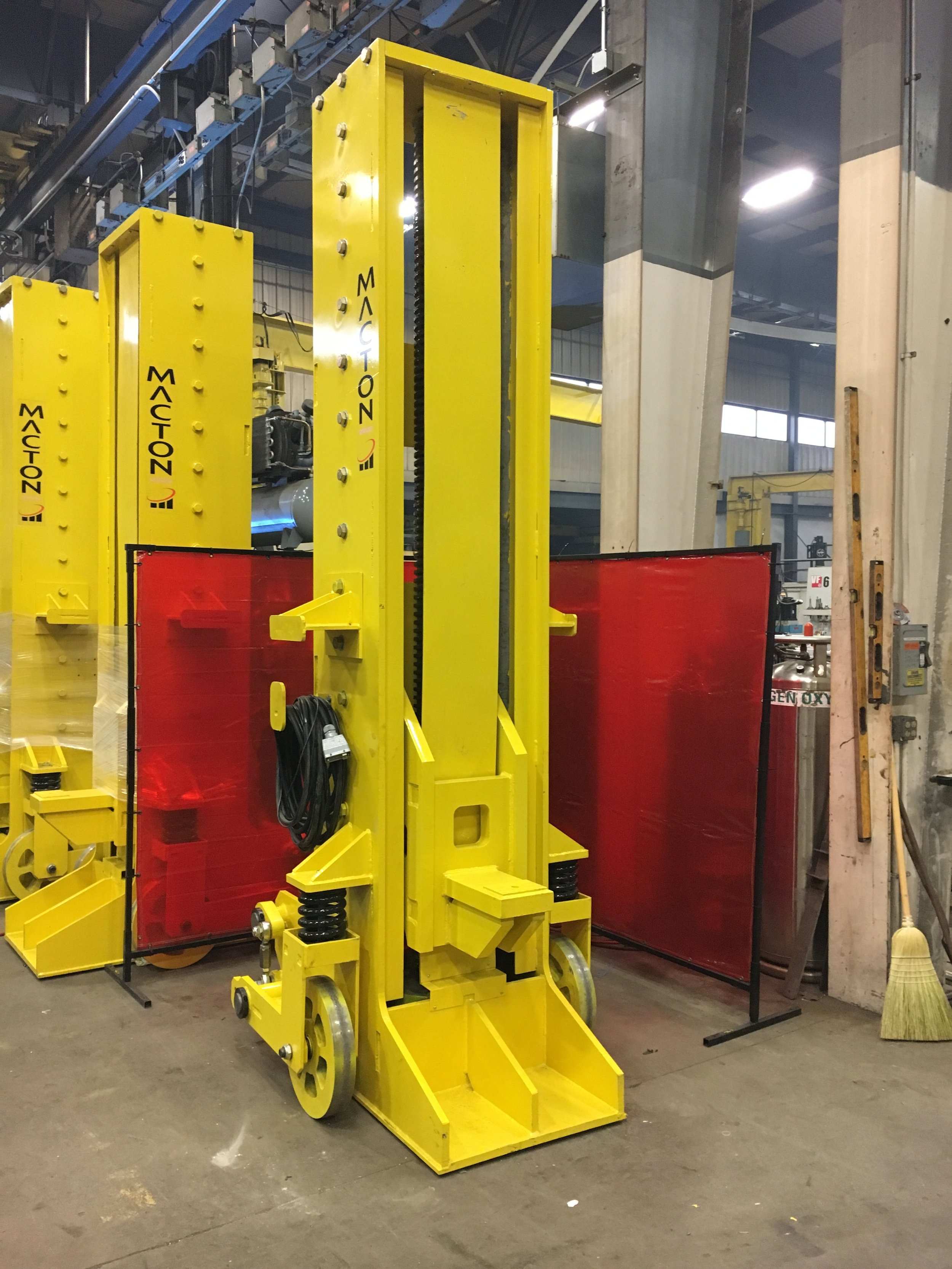
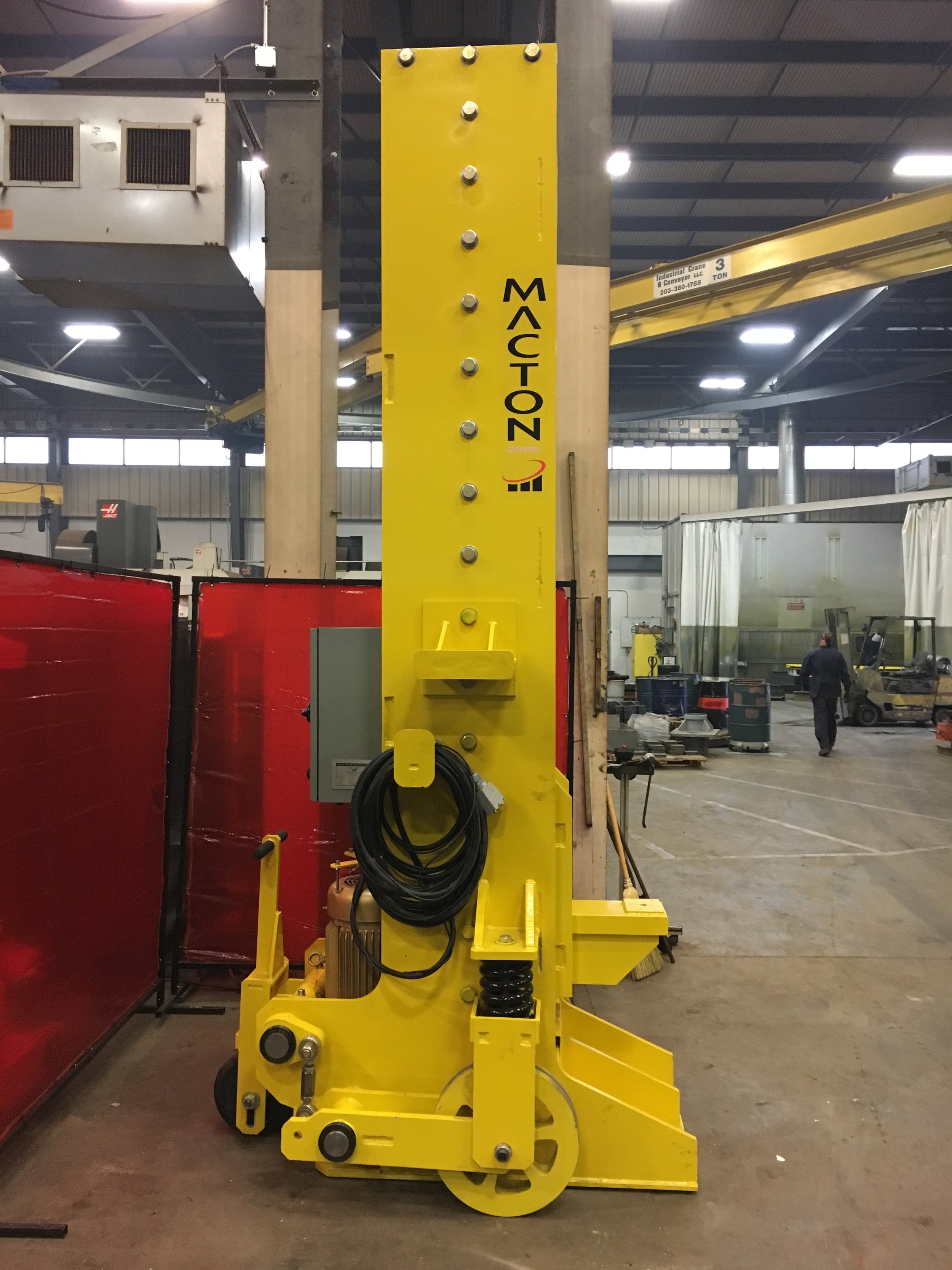
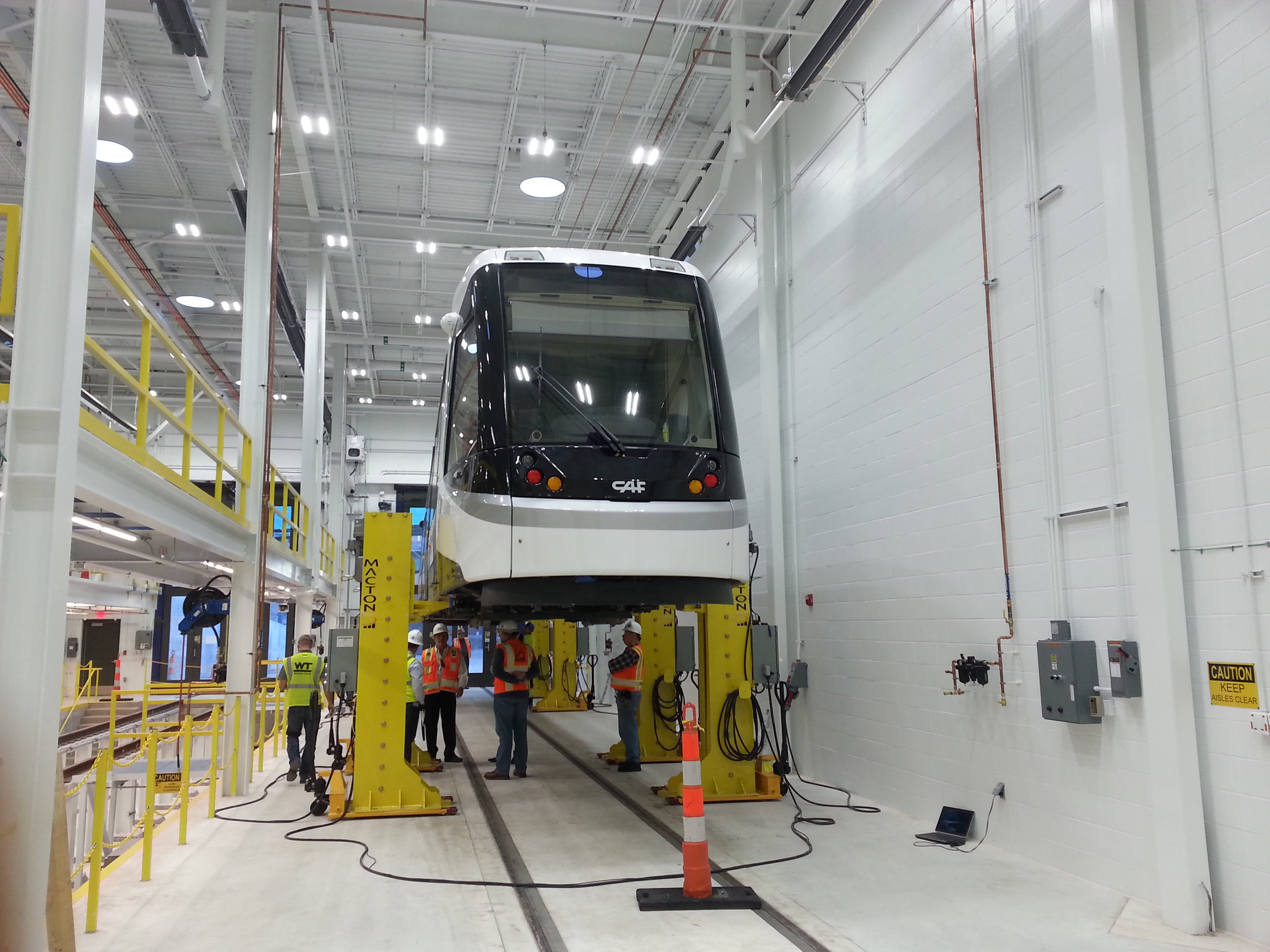
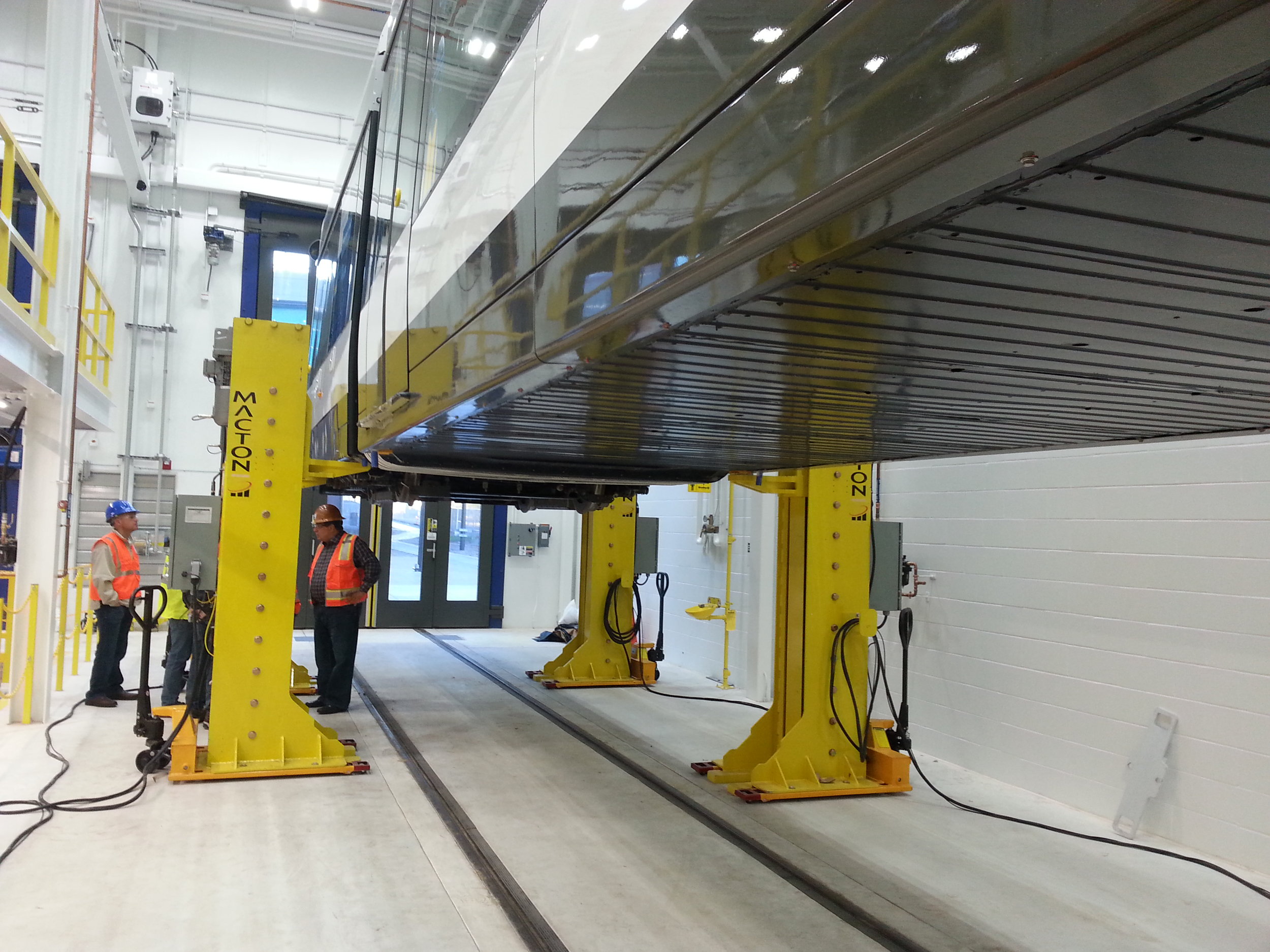
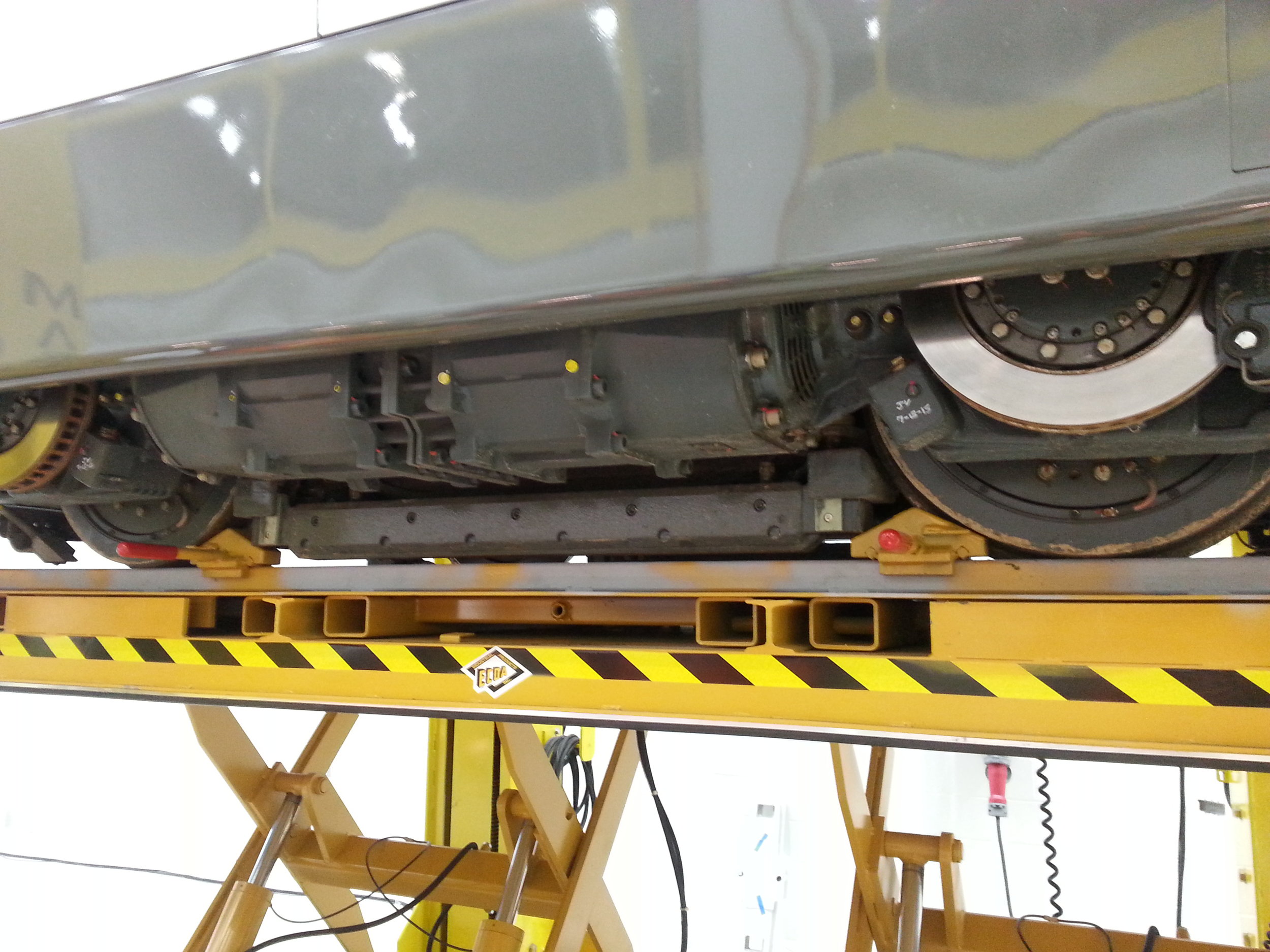

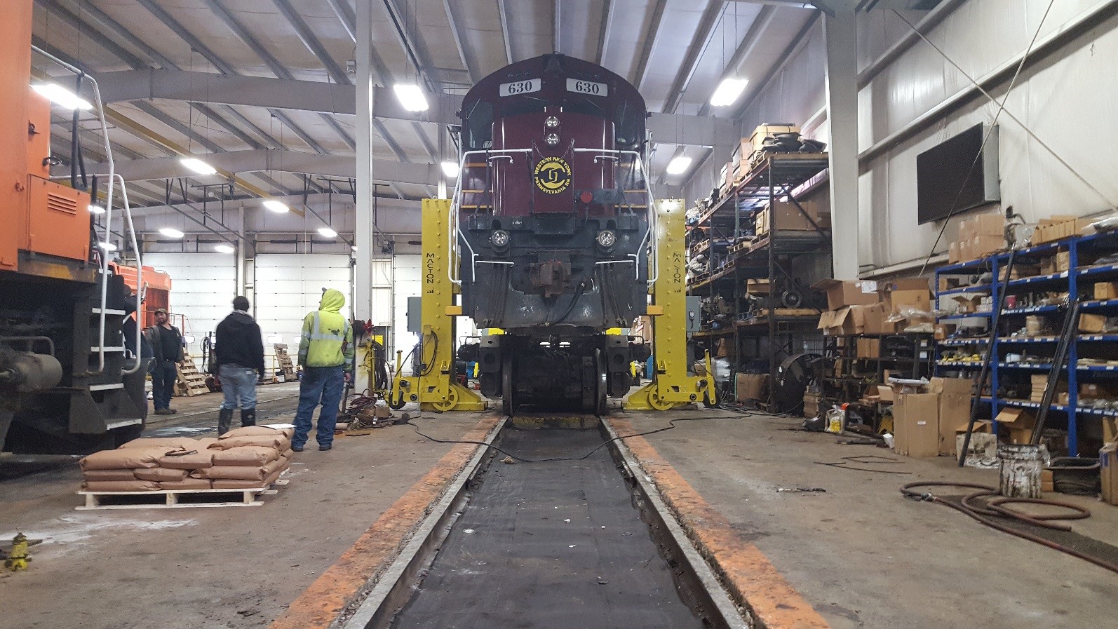

Portable Electric Jacks – Macton portable jacks deliver maximum floor space flexibility, transforming any location that can support substantial floor loading into a potential maintenance or repair area. Not only can a portable system be moved anywhere in the shop, but the individual jacking units in the system can also be independently positioned to adjust easily to a variety of support points on a railcar. Macton portable locomotive jacks operate individually or as a set for lifting locomotives or transit cars. When used as a set, the jacks are synchronized to assure safety and uniform travel among the jacks at all times. The electrically powered, machine screw drive system in the Macton jack is continuously self-locking to provide maximum security during lift operation. Locomotive jacks are complete with rubber-tired wheels and are easily moved and positioned under the vehicle. Jacks are available in capacities from 10 to 50 tons per jack with lifting heights to suit customer requirements. Control systems utilize a programmable controller for integration of safety interlocks and warning systems. Electrical features include upper and lower limit switches, load sensors on the jacking pad, motion control, group, pair and individual operation, and remote control operation.
KEY BENEFITS INCLUDE:
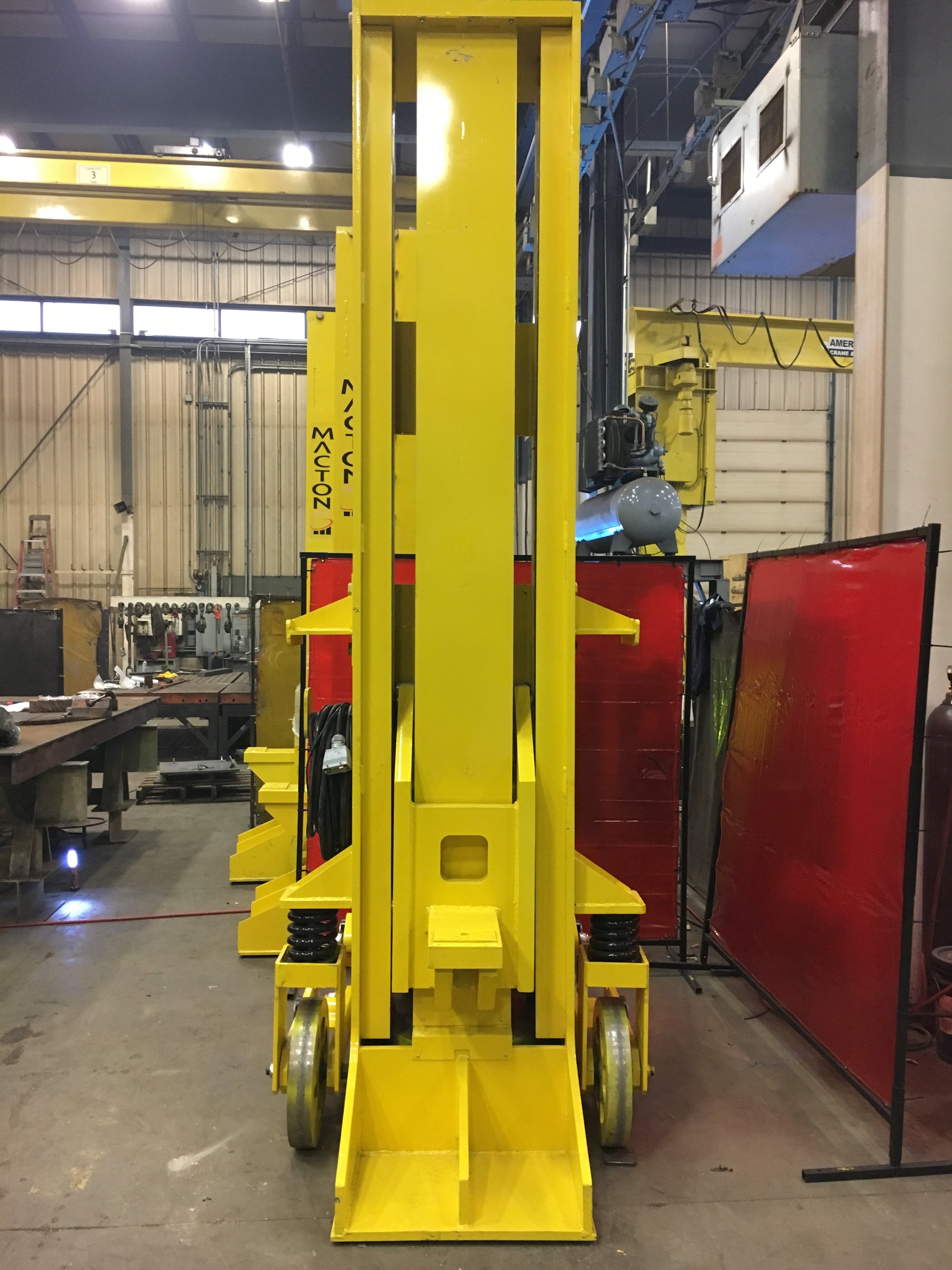
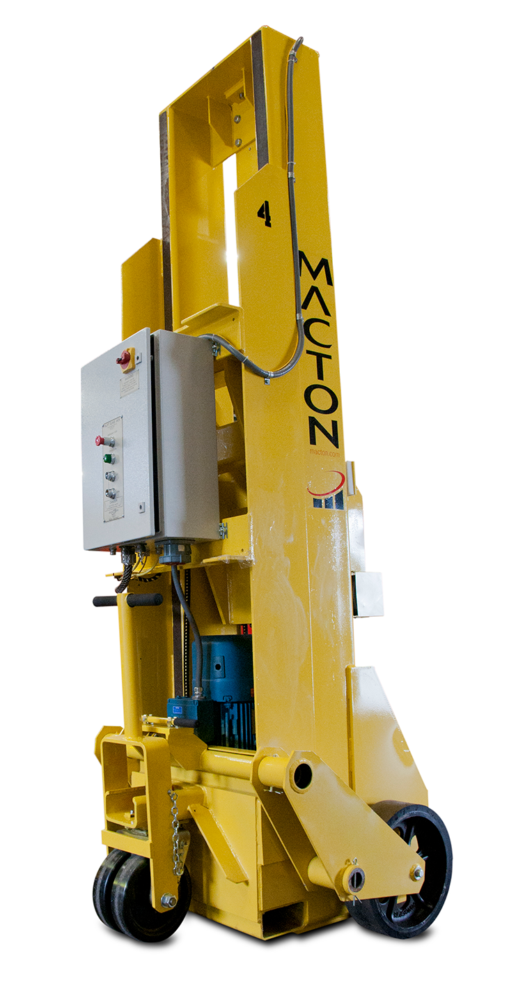
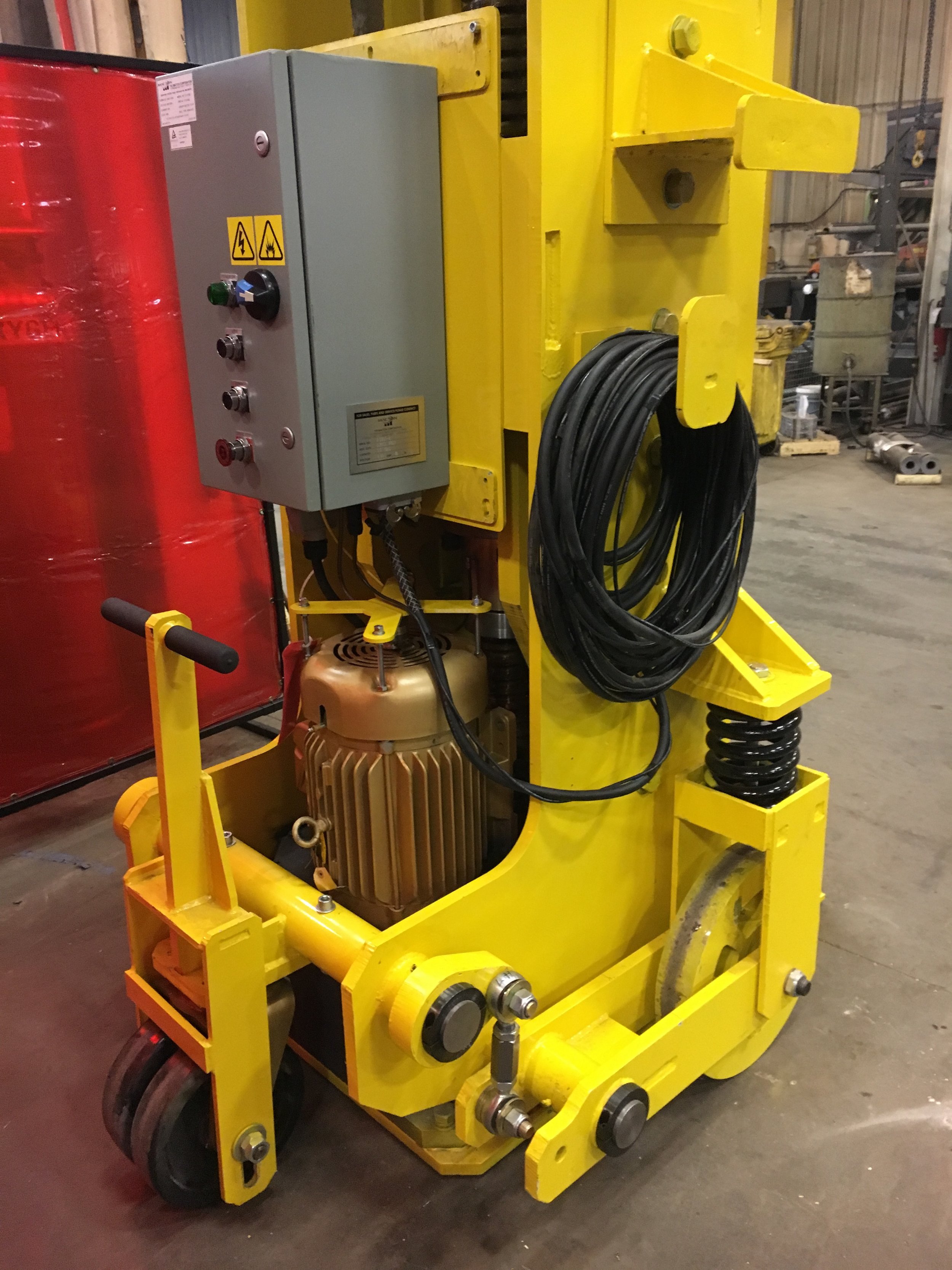
The screw on the Macton portable jack is housed inside of the steel column so that it is protected from damage in the shop environment. The front opening is covered with a protection band on the top and the bottom to keep the dirt and debris off of the lifting screw. Our competitors screw is outside of the column and is only protected by a bellow on the top of the screw.
The lifting carriage guide rollers on the Macton jack are housed inside the steel column, protecting them from damage.
The Macton portable jack bronze lifting nut is followed by a steel safety nut that will hold the load in the event of a bronze nut failure. A nut wear switch monitors the wear of the bronze load nut and will prevent the jack from raising if the bronze nut has worn past the allowable limit.
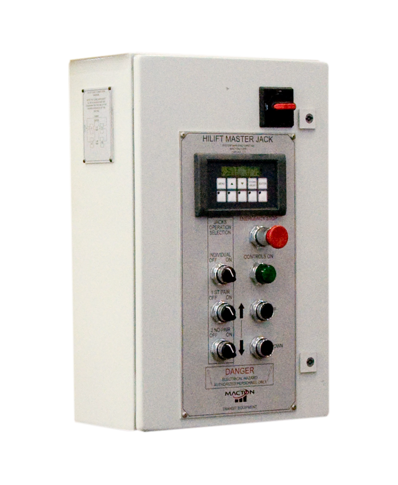
A Human Machine Interface LCD Screen on the primary panel provides troubleshooting information in the event of a system fault. In normal operation mode, this panel may be used to gain information about the lifting system including schematic and program information. If the system faults, the Screen will show an error message to indicate what component has caused the fault.
Paired Operation A set of four jacks can operate as a set of four, in pairs or individually by turning a selector switch on the Master control box.
For a full list of features and benefits, click on the tabs below.
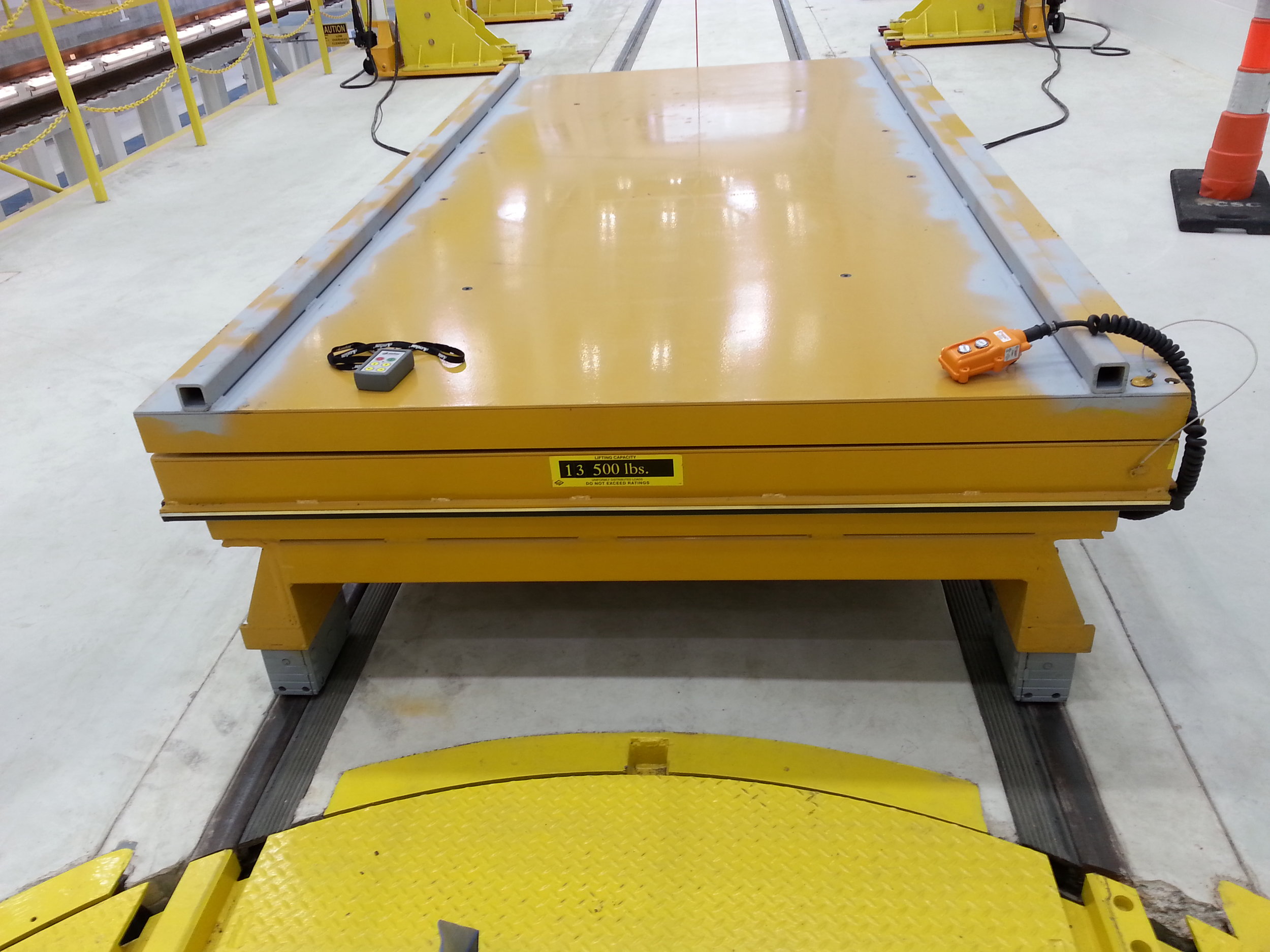
Maximum Capacity |
20 tons per jack, or 80 tons (72.5 metric tons) per set of 4 jacks |
Minimum Lifting Height |
6” measured from the finished floor up to the top of lifting pad |
Maximum Lifting Height |
7’-8” (92”) (other ranges available upon request – see below) |
Lifting Stroke |
7’-2” (86”) (other ranges available upon request – see below) |
Lifting/Lowering Speed |
10” per minute |
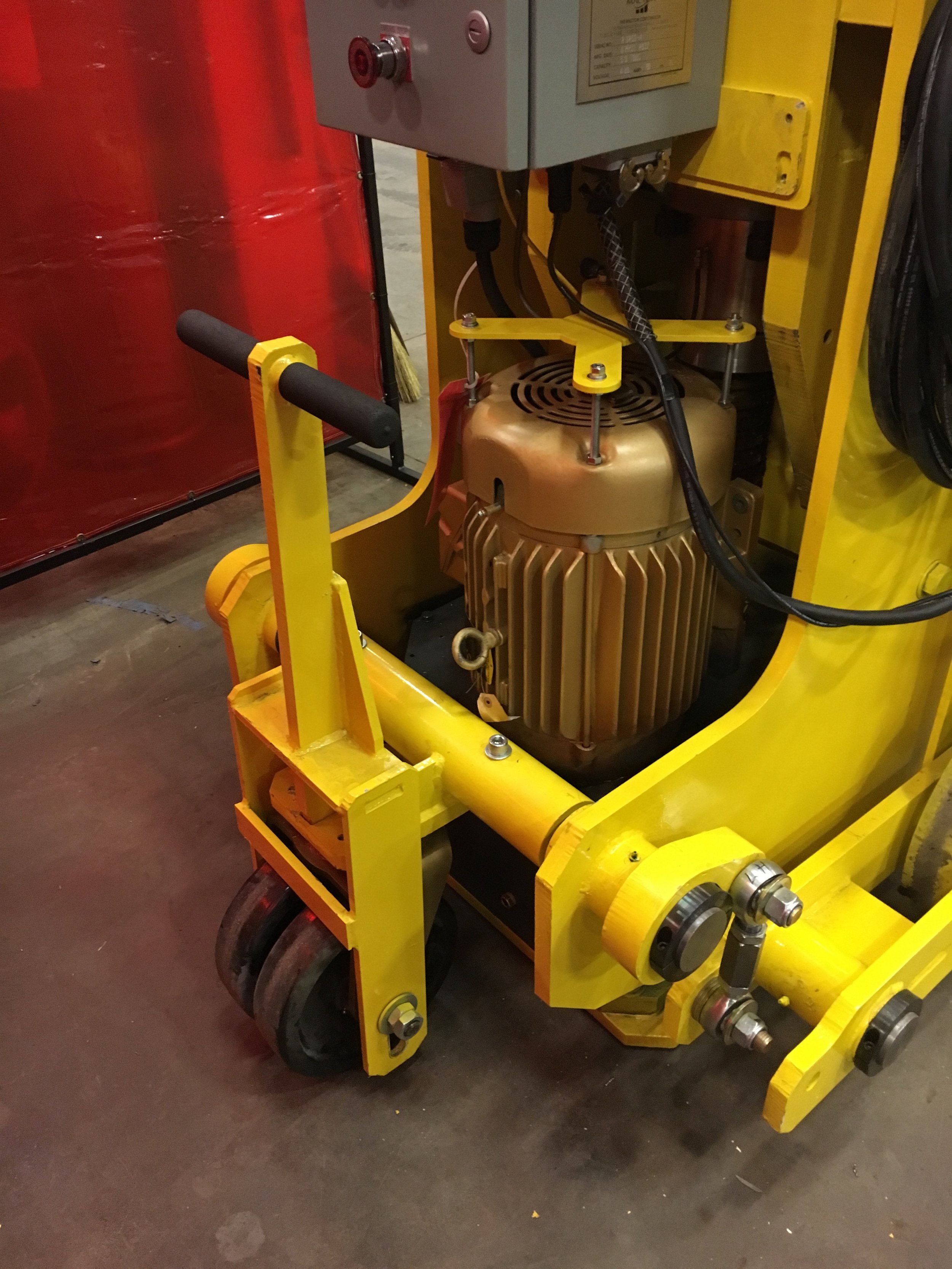
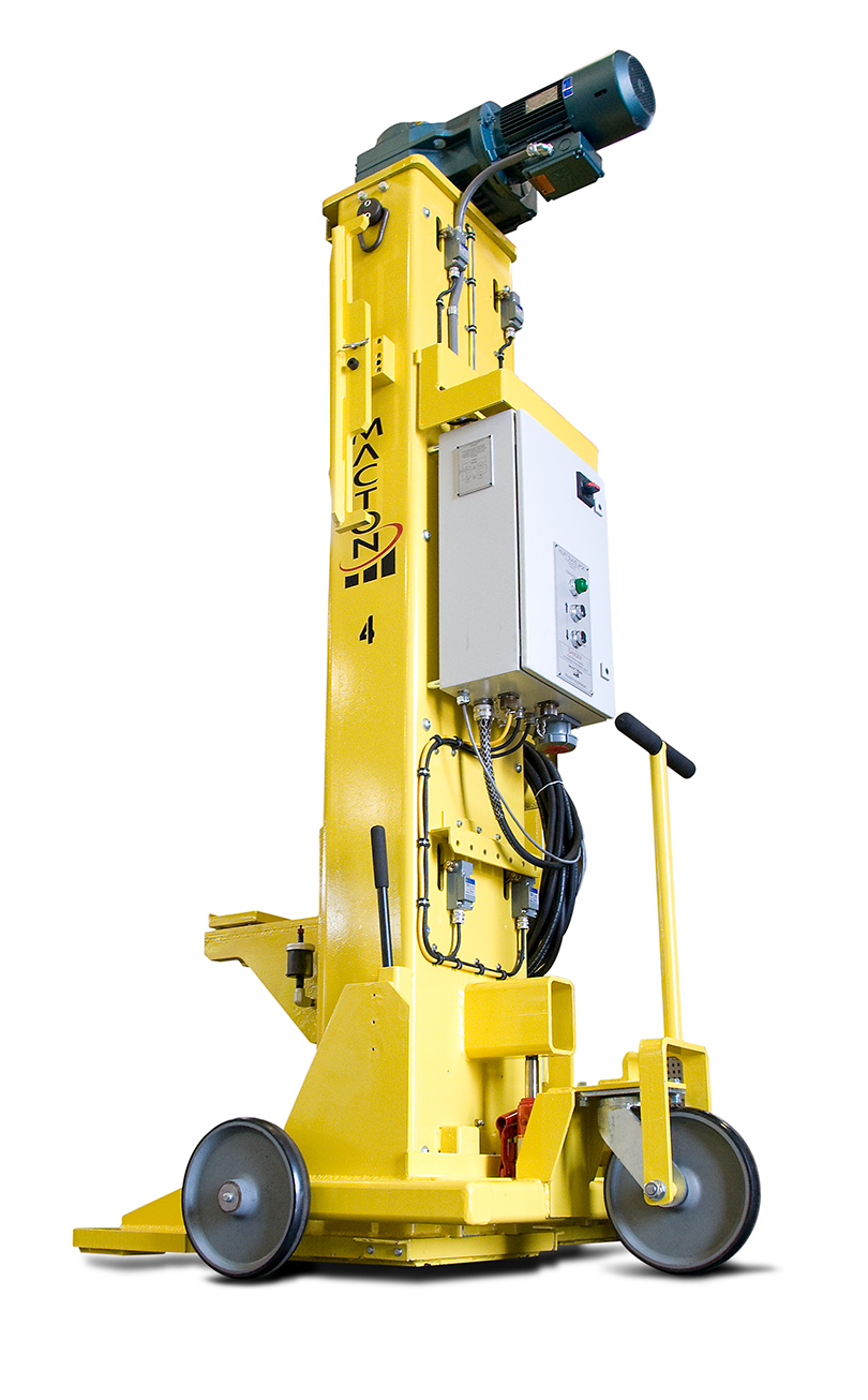
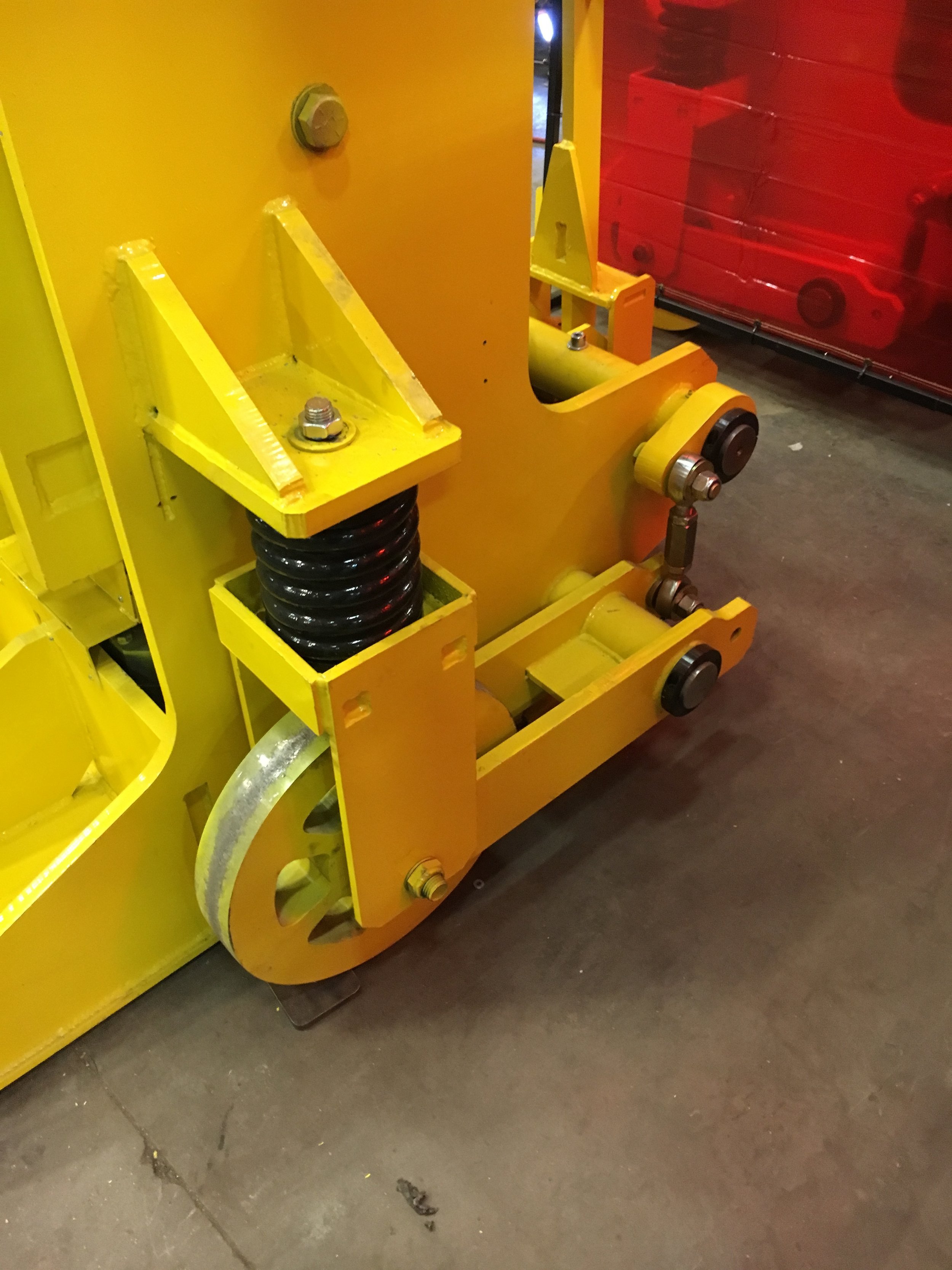
Ease of Portability |
Wheels at the base are lowered when the jack is in the full down position, to allow an operator to position the jacks manually using the rear wheel with attached handle bar to steer |
Jacks may also be moved with a crane using the main lifting lug at the top of each jack and by a fork truck using slots in the base of the jacks |
|
Safety Features |
Self-Locking Lifting Nuts – Self-locking screw jacks with bronze nuts are used – the system is designed to be fail-safe so as to support the load in the event of power or mechanical failure (they require power to raise or lower) |
Steel Safety Nuts – Screw jacks include a steel follower safety nut, to support the load in the event that the bronze lifting nut fails |
|
VFD with Encoder Counts – Each jack unit has a variable frequency drive and an absolute multi-turn encoder mounted directly on the motor to maintain synchronous lifting and lowering heights of all of the hoist motors in the system. |
|
Absolute Height Position Sensing – In addition to the encoder system referred to above, upward and downward motion of the lift is also monitored and controlled using an absolute height position sensor with a steel measuring cable that monitors the travel and position of each guide cylinder throughout the entire hoist lifting operation (as well as lowering). |
|
Controls – Mushroom-type emergency stop button shuts down control system when activated; also, “dead-man” type controls make sure the controls require constant pressure to operate; in addition, electrical interlocking of motors exists so that the breakdown of one automatically shuts down power to the other jack motors |
|
Lubrication |
System provides automatic screw and nut grease lubrication |
Screw Protection |
Screw protected by the steel structure surrounding it (eliminates the need for separate protective boots) |
Dimensions |
Jack Height is 11’-2 ½“ (134 ½”) |
Jack Width is 2’-9 ½” (33 ½”) |
|
Jack Depth is 4’-10.5” (58.5”) |
|
Lifting pad dimension is 5” deep and 6” wide |
|
Clearance distance from the forward-most point on the jack lifting pad to the main jack column is 13.8” |
|
Paint Finishes Used |
Steel structure coated with one coat of rust inhibiting primer followed by two top coats of yellow industrial grade polyurethane enamel |
Weight |
Approx. 2,500 lbs per jack |
Gearbox Oil for Temperature Extremes |
Mobil SHC 630 premium synthetic oil (or its equivalent) used to protect gearbox from extremes in outside temperature (cold or hot weather) –jacks can operate in an ambient temperature range from 25°F to 100°F |
Power Required |
480V, 3 phase, 60Hz (other voltages available upon request) |
Motor |
5 horsepower, NEMA D, 1750 RPM with electromechanical brake |
Control System |
Each set of four jacks has one master jack and three secondary jacks Control box enclosures and motor starters are NEMA 12 rated |
Master Control Box |
Green pilot light to indicate when the control system is on |
Dead man type UP and DOWN push buttons |
|
Two position selector switch to operate the jacks either INDIVIDUALLY or in SYSTEM mode |
|
Two position selector switch to enable Pair mode operation |
|
EMERGENCY stop push button |
|
Operator Interface panel |
|
Receptacles for control cables and remote control |
|
35-foot power cable |
|
Secondary Control Box |
Green Pilot light to indicate when the control system is on |
Dead man type UP and DOWN push buttons |
|
EMERGENCY stop push button |
|
50-foot interconnecting cables with quick disconnects and an oil resistant jacket are supplied to connect the secondary jacks to the master jack |
|
Diagnostic Message Display |
LED display advises if certain faults have been tripped on the jacks |
Position Encoders |
Synchronizes the lifting carriages of all 4 jacks, to ensure that all lifting carriages stay within 1/2” between jacks on the opposite sides of the vehicle and 1” between jacks on the same side of the vehicle |
Nut Wear Indication |
Sensors to advise if the bronze nut has worn past an acceptable level |
Warranty Period |
5 years – the most extensive warranty in the industry, demonstrating how confident we are in the performance and durability of this equipment |
O&M Manual |
Operation & Maintenance manual in English provided in electronic format |
Quality Procedures |
All materials and work done on the system are carefully monitored under an ISO 9001:2008 certified program and 100% designed and built in our facility in the United States (we don’t reassemble systems built in other countries); all welding is performed in accordance with ANSI/AWS Structural Welding Code D1.1 standards and is inspected and approved by a Certified Welding Inspector qualified under Section 6.1 of the AWS current specification |
Pre-Shipment Factory Testing |
Equipment is fully assembled and operationally tested at the factory prior to shipment – at this time, the owner’s representative may, at their option, inspect, operate and dimensionally check the equipment prior to shipment to confirm the owner’s needs are met |
Onsite Startup & Training |
Factory-trained technician provided for onsite startup and training at no added cost (all field labor and travel costs included in equipment price) |
Longer Cable Lengths |
Added lengths on power or control cables (e.g., 85-foot lengths between jacks) |
Remote Pendant |
One (1) NEMA 12 push button pendant with UP/DOWN control is supplied; the pendant plugs into the master jack control panel; individual control of each jack is disabled when the pendant is engaged; cable shall be at least 10 feet long |
Changes in Lifting Stroke or Overall Jack Height |
Changes can be made upon request in either the lifting stroke or the jack height (such as lowering the jack height if the facility has height restrictions, such as an overhead work platform) |
Obstacle Detection |
Stops downward travel of the carriage when an obstruction is inadvertently left under the lifting carriage |
Load Pad Indication |
Sensors to advise if the load pad on the lifting carriage is under load |
Warning Lights / Horns |
Warning lights and/or horns mounted on the control panel to advise that equipment is in operation |
Touch Screen Display |
Touch screen controls on the master control panel which provide enhanced diagnostic information to the operator |
Wireless Control System |
Wireless control system to eliminate the need for control cables (power supply cables will be included to supply power to all jack columns) |
Control Box Heating |
Heating elements in control box for using equipment in a cold environment |
Support Stands |
Support stands to allow multiple vehicles to be worked on at one time |