
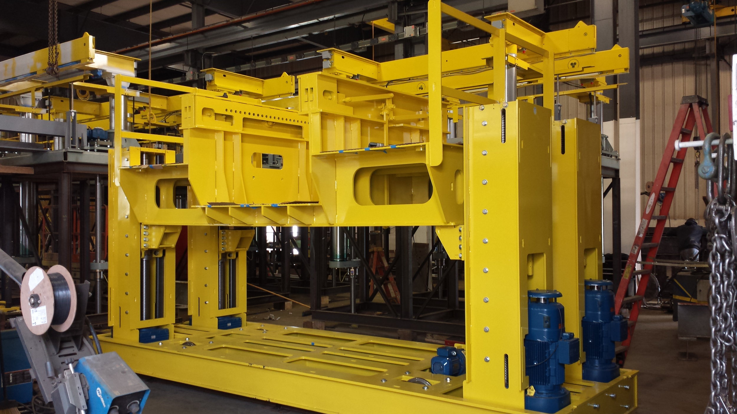
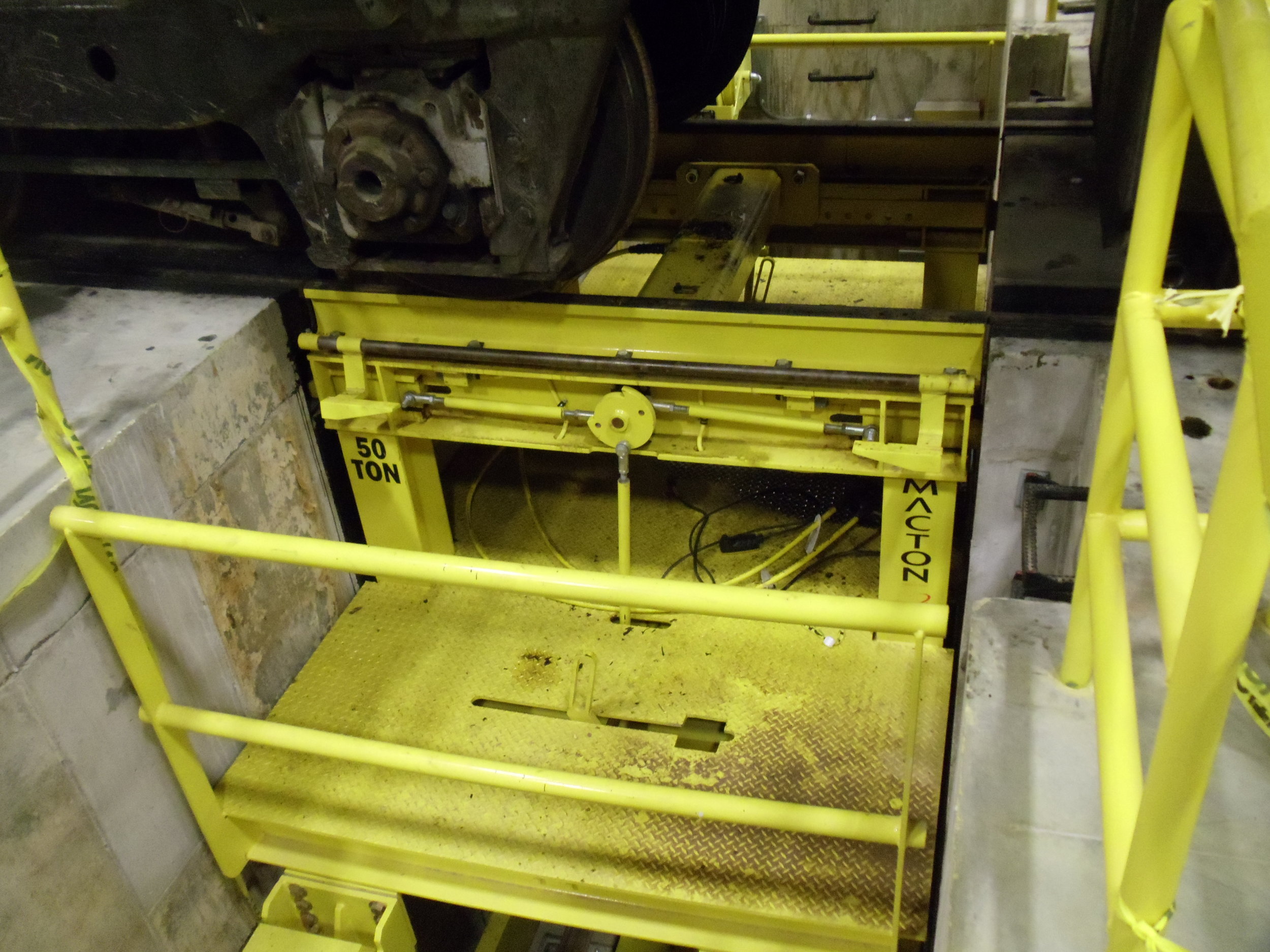
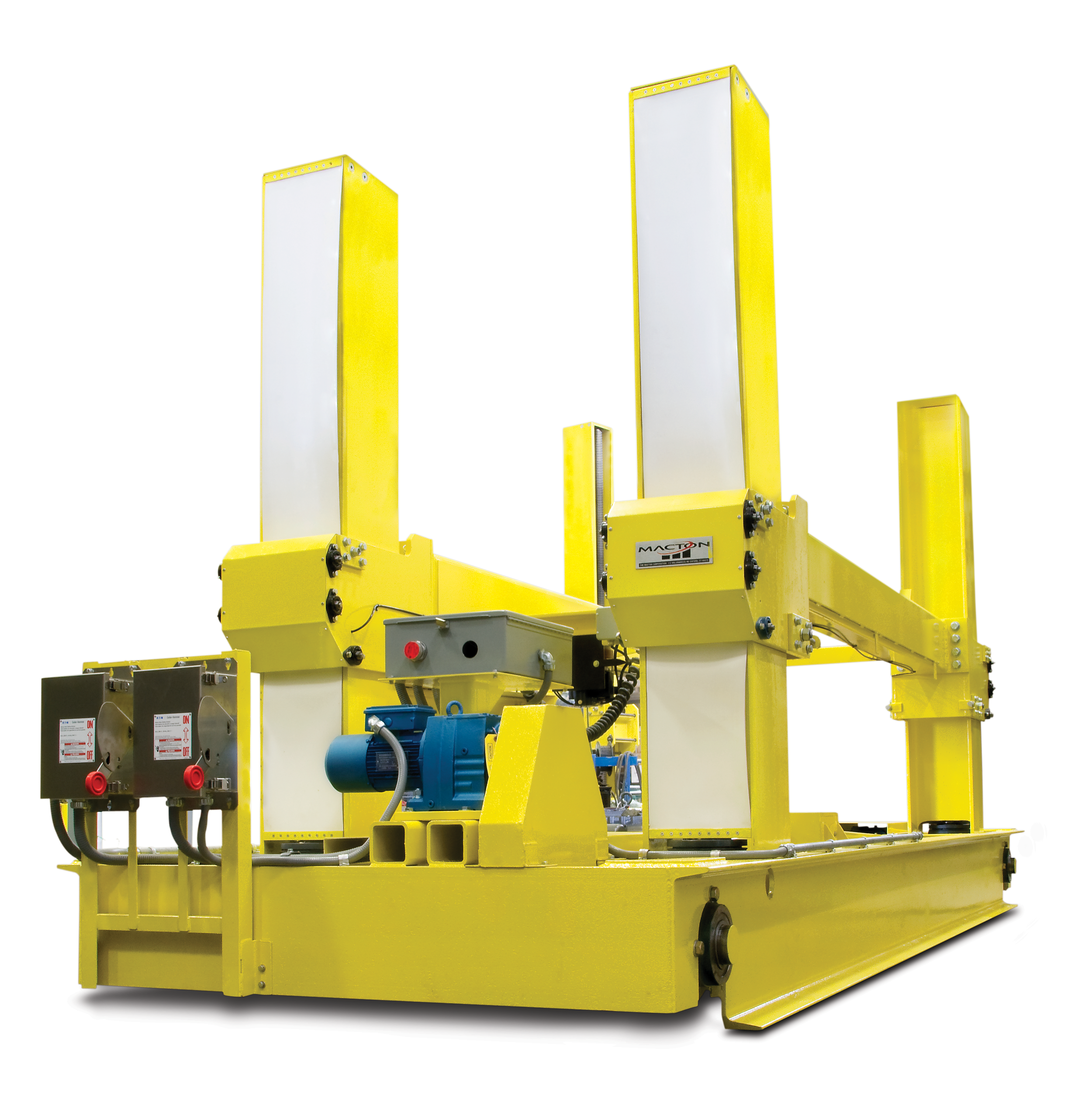
Single Axle Drop Tables – Macton single axle drop tables are designed for rapid change out of locomotive combination wheel set and motor assemblies. The drop tables are capable of operating with multiple service tops. Control systems utilize PLC for integration of interlocks to provide maximum operator and machine safety. Automatic lubrication systems maximize lift system component longevity.
KEY BENEFITS INCLUDE:
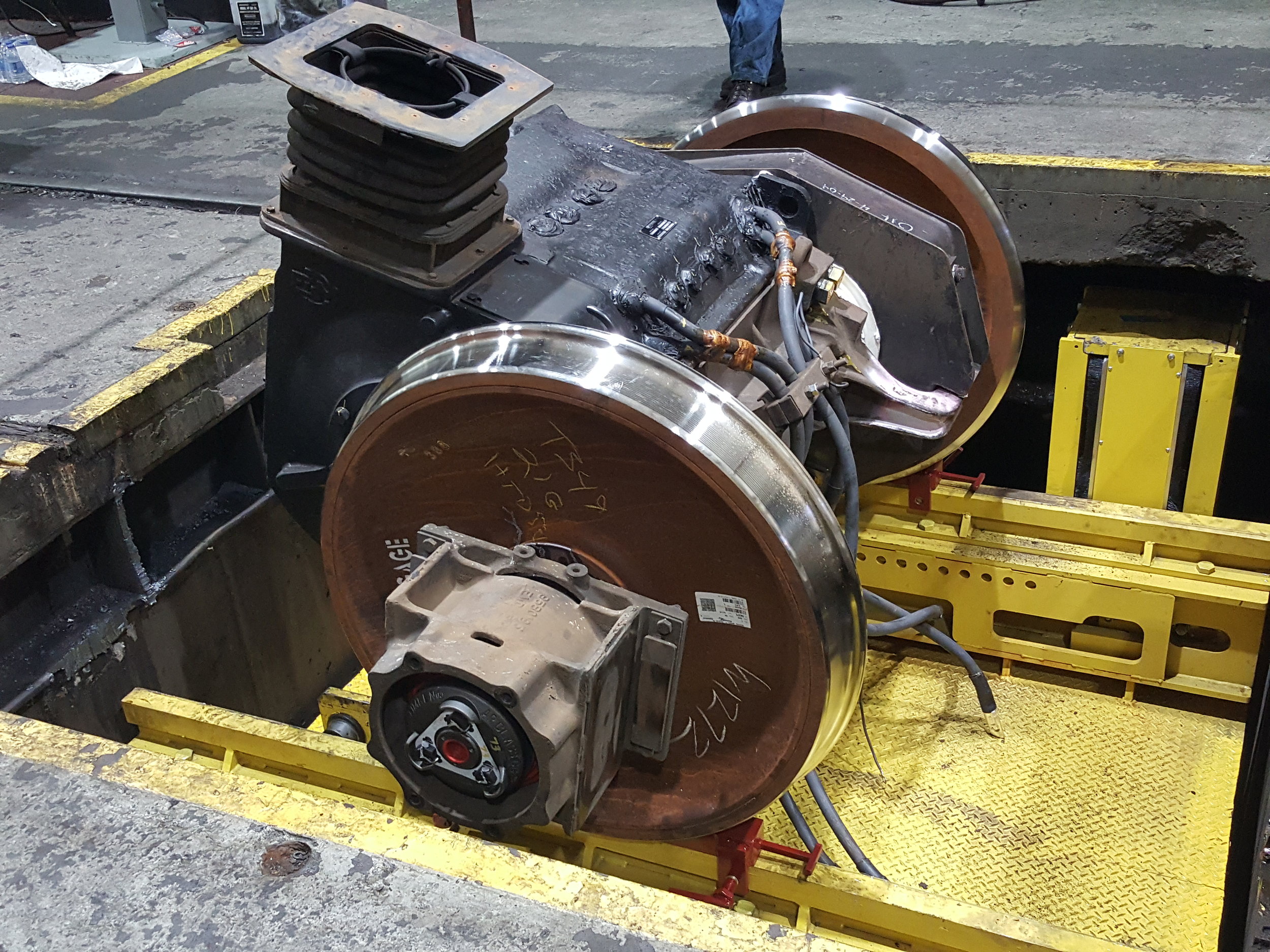
- Capable of changing out single axles with traction motors. More cost effective and quicker installation time compared to full truck system.
- Four (4) Self-locking machine screws with bronze nuts and steel safety follower nuts.
- Independent lifting columns with variable frequency drives (VFD) and absolute multi-turn encoders. Absolute height position sensing also included on each column as an additional safety device.
- Automatic table positioning using absolute laser feedback allows operator to select destination and traverse table with accurate precision with the touch of a button.]
- Operator Station provides drop table location and fault information on HMI display. Wireless remote controller provided with emergency stop pushbutton.
For a full list of features and benefits, click on the tabs below.
Maximum Capacity |
50 tons (approx. 45,000 kilograms) |
General Capabilities |
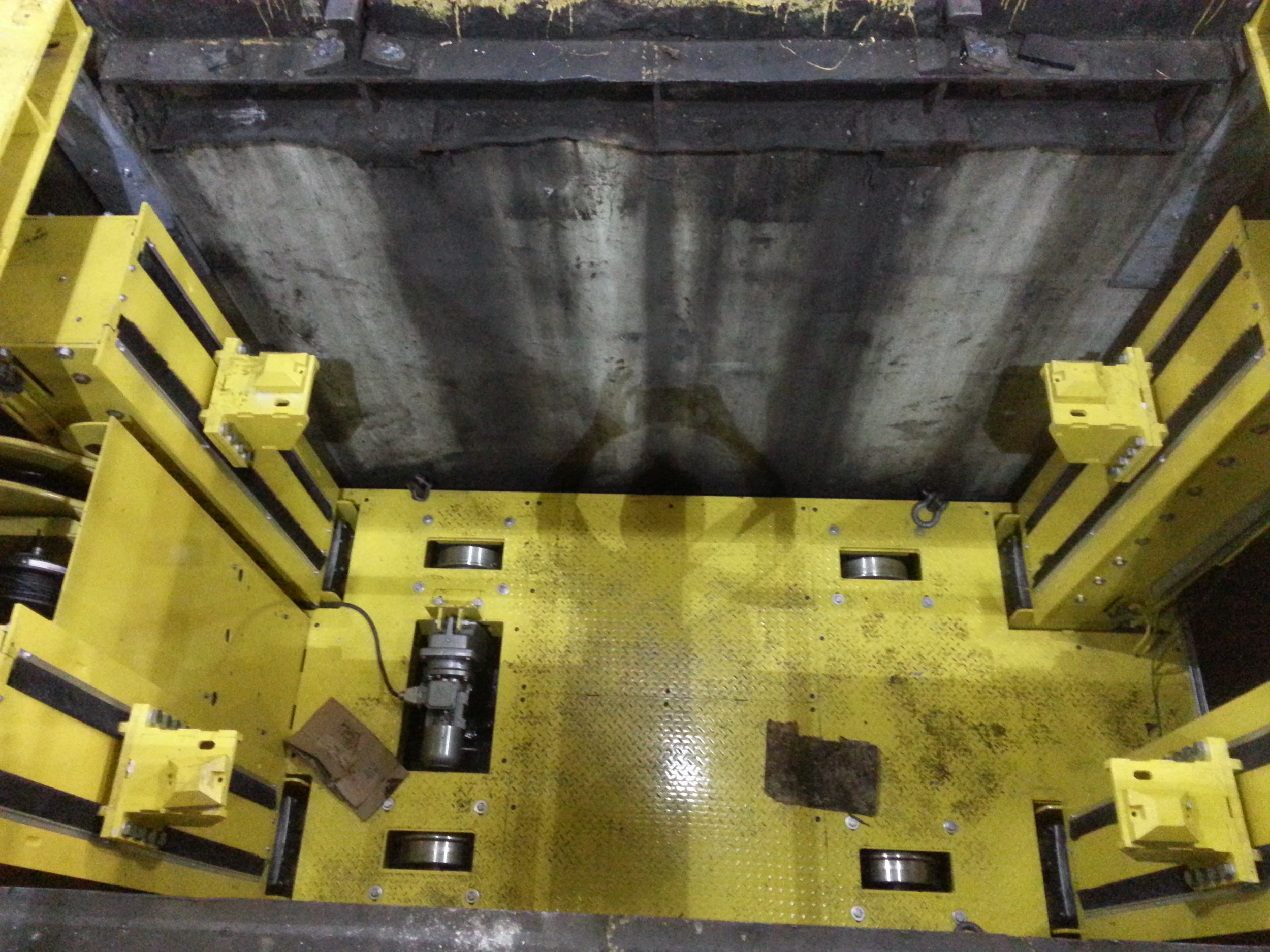
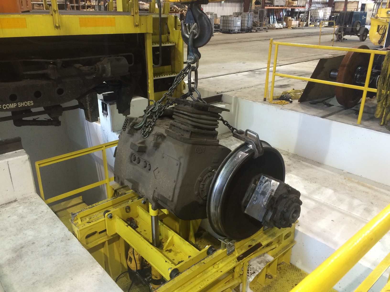
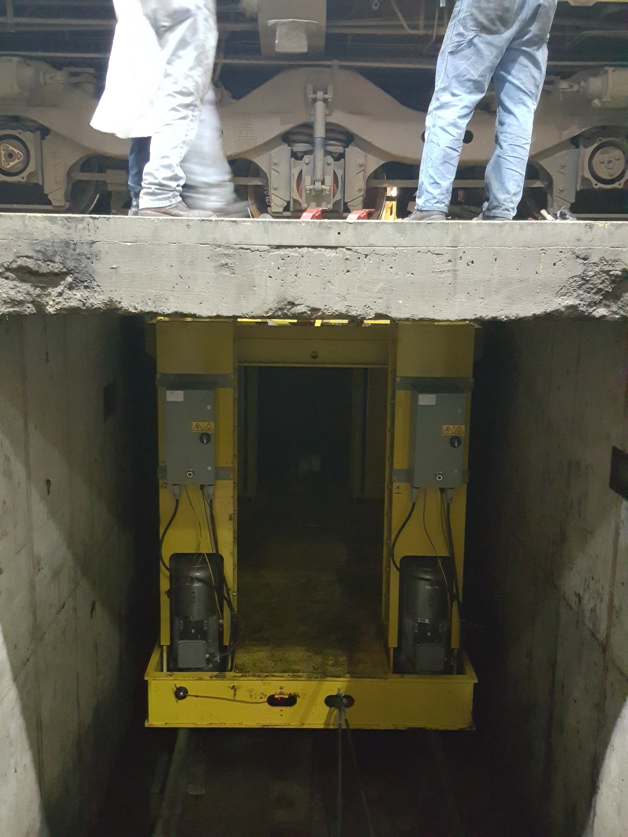
Drop table system will handle the change-out of both wheelsets and traction motor combos; it is capable of lifting 50 tons one inch (1”) above the top of the rails to allow such wheelsets and combos to be disengaged from the trucks, and then have the lifting carriage lower to the bottom of the service track pit and then traverse over to the release track, where it can then be raised up to move the wheelset or combo off the release track; the process can then be repeated in reverse to put a new wheelset or combo back into the rail vehicle |
Lifting/Lowering Speed |
3.0 feet per minute for lifting or lowering |
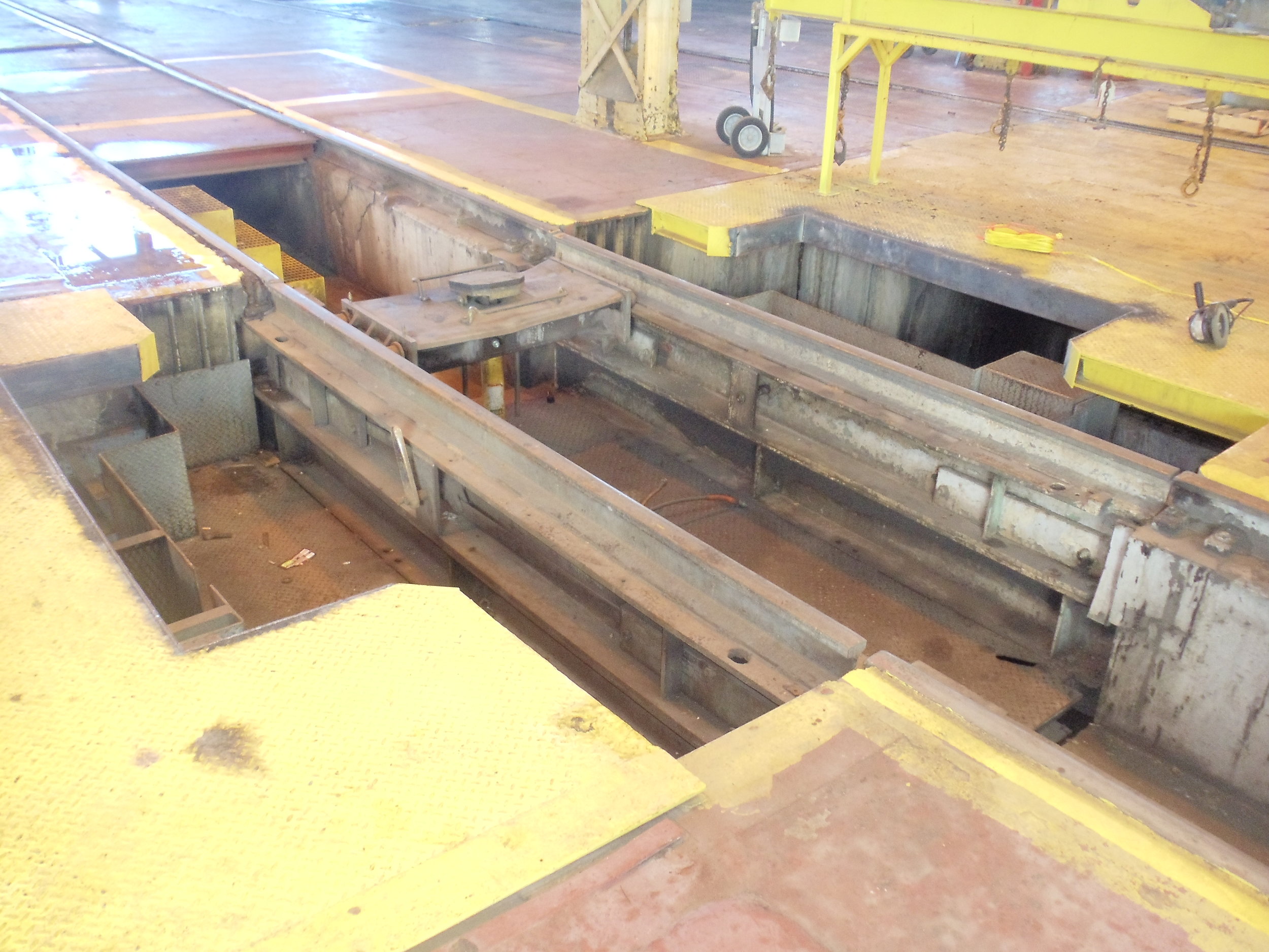
Traversing (Racking) Speed |
Carriage racking speed is controlled by a variable frequency drive; while traversing through the tunnel the speed is approximately 30 feet per minute and slows to 3 feet per minute when approaching the service and release area |
Open Release Area |
An open release area (i.e., no release top) is assumed as part of the standard system (a bascule top or canopy top is available as an option – see options below) |
Screw Jacks |
Drop table has four (4) self-locking ACME-thread machine screw jacks, each driven by its own independent gearmotor system |
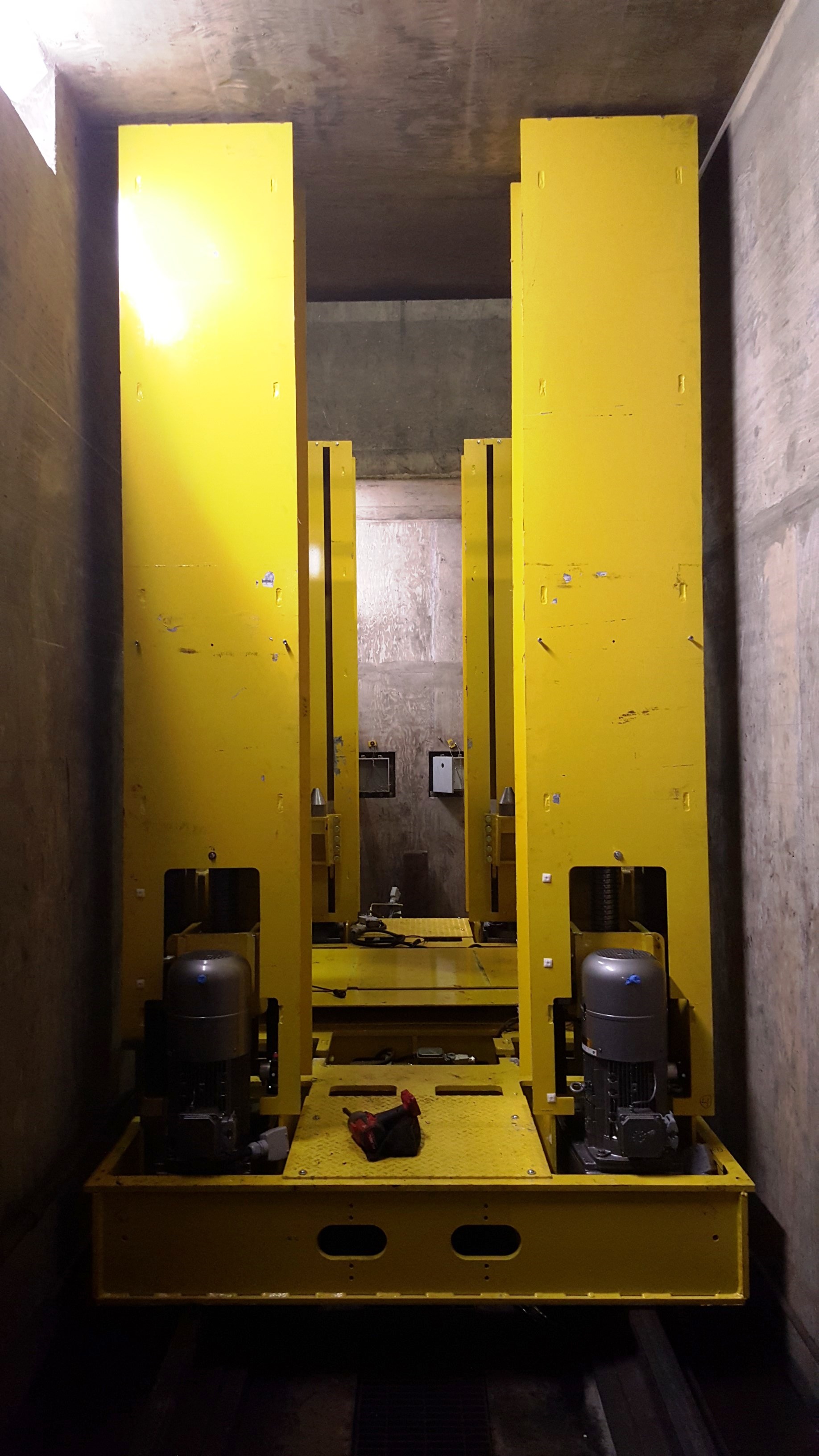
Vertical Guide Supports |
Vertical travel of the lifting carriage is guided for the entire travel length by steel rollers against guide columns to prevent side loads and enhance screw life |
Track Gauge |
U.S. version is 4’ 8-½” (56.5”); Canadian version is 4’ 10-7/8” (58.875”) |
Service Top Locking Bars |
Manually-operated locking bar system for support of service top when drop table is not in use |
Controlled Upper Racking of Service Top |
Controls allow the drop table to rack approximately 1” from centerline in either direction within the upper range of lifting travel to allow for easier alignment of wheelsets and traction motors |
Safety Features |
Self-Locking Lifting Nuts – Self-locking screw jacks with bronze nuts are used – the system is designed to be fail-safe so as to support the load in the event of power or mechanical failure (they require power to raise or lower) |
Steel Safety Nuts – Screw jacks include a steel follower safety nut, to support the load in the event that the bronze lifting nut fails |
|
VFD with Encoder Counts – Each jack unit has a variable frequency drive and an absolute multi-turn encoder mounted directly on the motor to maintain synchronous lifting and lowering heights of all of the hoist motors in the system. |
|
Absolute Height Position Sensing – In addition to the encoder system referred to above, upward and downward motion of the lift is also monitored and controlled using an absolute height position sensor with a steel measuring cable that monitors the travel and position of each guide cylinder throughout the entire hoist lifting operation (as well as lowering). |
|
Controls – Mushroom-type emergency stop button shuts down control system when activated; also, “dead-man” type controls make sure the controls require constant pressure to operate; in addition, electrical interlocking of motors exists so that the breakdown of one automatically shuts down power to the other jack motors |
|
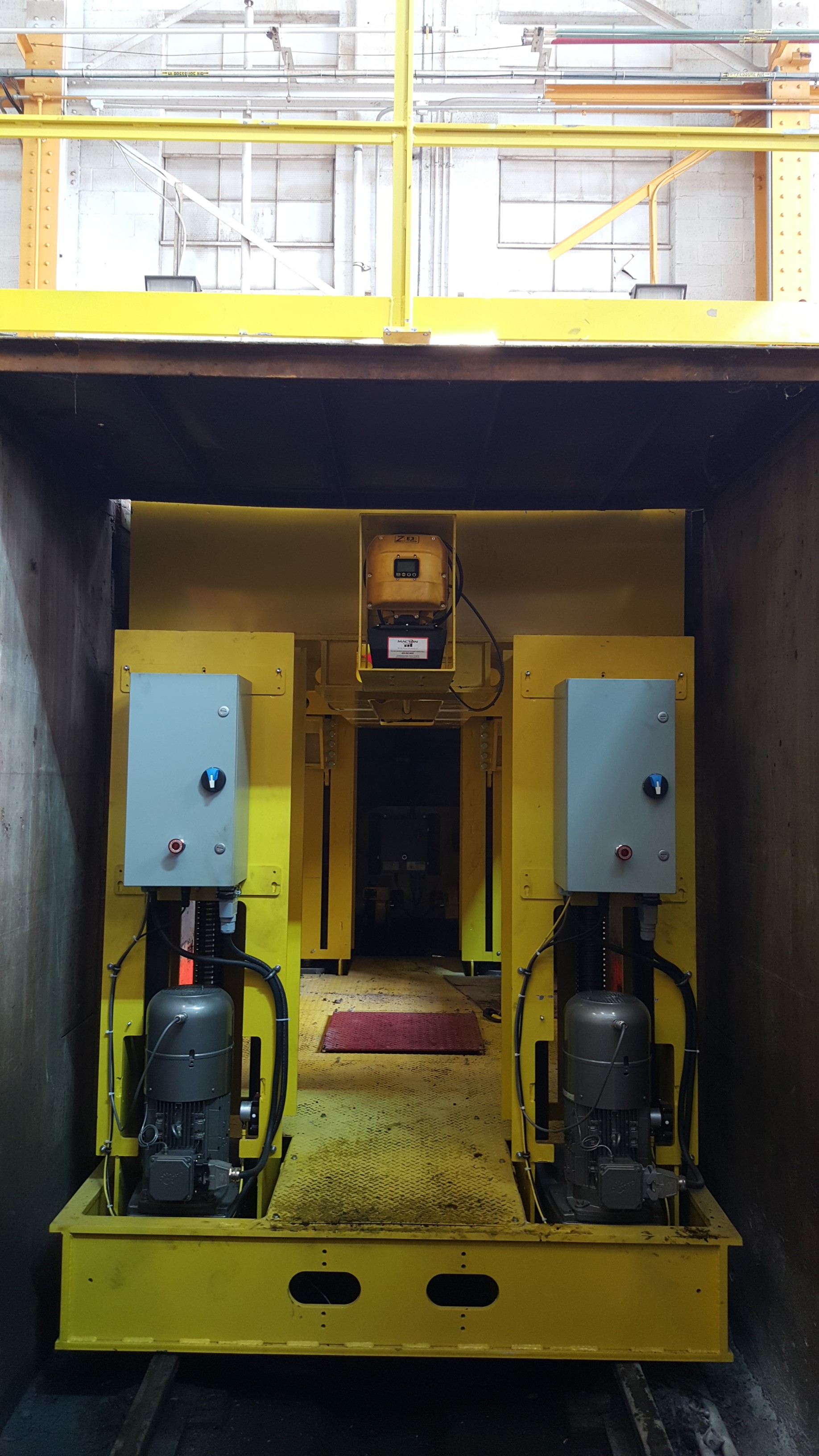
Screw Protection |
Each lifting screw is enclosed with a stationary cover and brush guards for maximum protection from debris and contamination |
Modular Sections |
Drop table built in modular steel sections, allowing for a quick and reliable assembly at the jobsite, as well as for better control of the overall equipment quality |
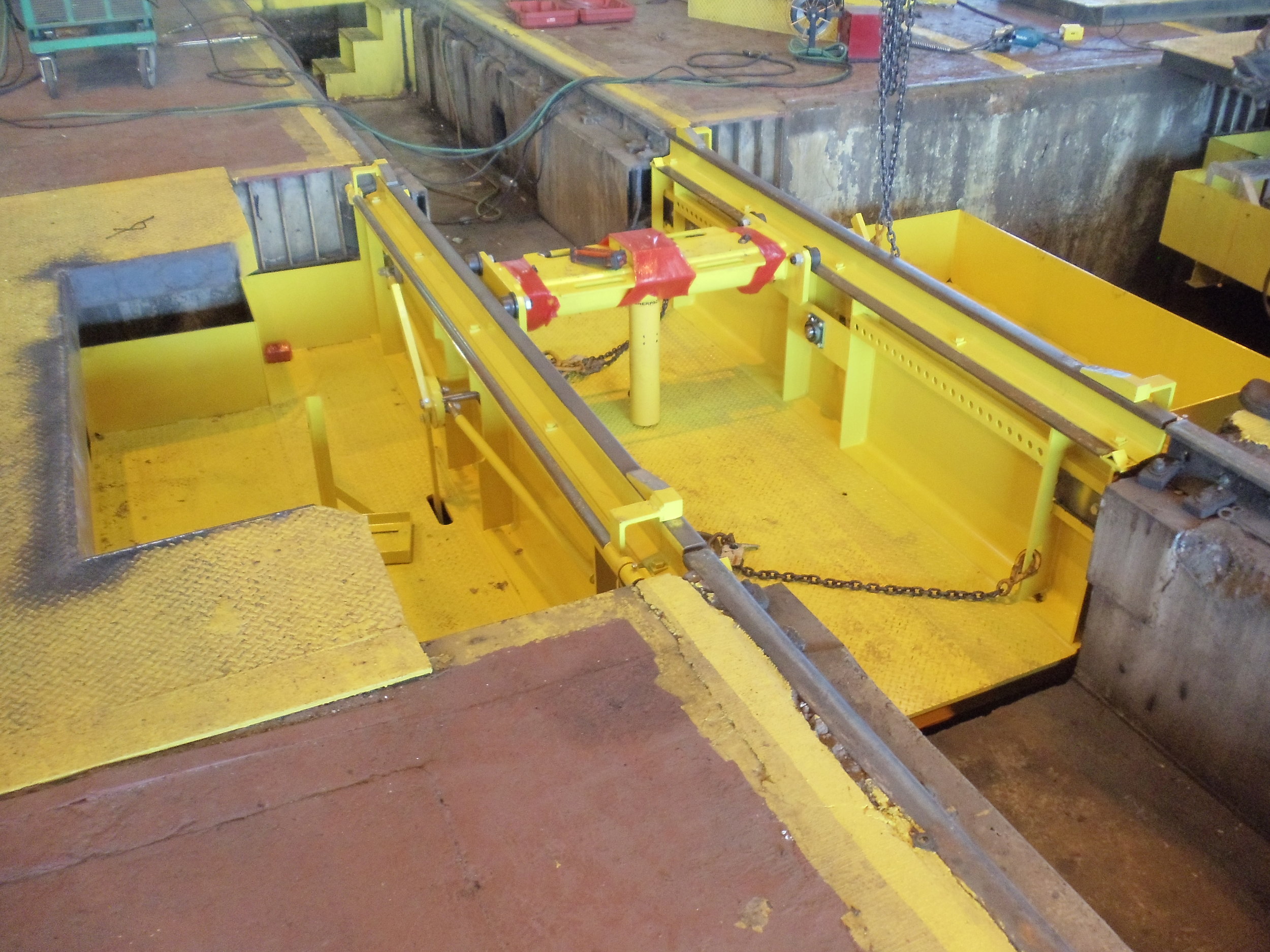
Traction Motor Dolly |
System includes a traction motor dolly supported on steel rollers to provide support of traction motors during the removal and replacement of individual wheel sets which have traction motors. The dolly head can be lifted or lowered to assist in the removal and replacement of these items, and it plugs into an 110V outlet (to be provided by customer). The lifting cylinder comes equipped with one of a variety of fixtures that can accommodate a wide range of traction motor styles and manufacturers (customer can order additional fixtures, if needed). |
Wheel Chocks |
Manual wheel chocks are provided on each rail to limit the movement of wheel-sets |
Pit Rail |
To be provided and installed by others (optional pit rail available – see options below) |
Finishes |
Steel structures are coated with one coat of rust inhibiting primer followed by a top coat of yellow industrial grade polyurethane enamel |
Embedments |
Fabricated steel embedments for the concrete foundation are provided prior to equipment installation (to be installed by others) – these include embedments for the service top locking bars and, if needed, any guide frames for pit covers |
| Lifting Motor Used | An electric brake motor drives each of the lifting gearmotors; each uses 480V, three-phase, 60Hz power (other voltages available) |
| Traversing Motor Used | An electric gearmotor with brake and VFD (to ensure accurate and repeatable positioning) drives the traversing operation; it uses 480V, three-phase, 60Hz power (other voltages available); absolute laser feedback is used to further ensure the accurate positioning of the drop table system within the pit |
| Control System | Complete control system including (i) operator’s control station with a touch-screen operator interface that displays operating and fault messages to help the operator more easily understand and use the equipment, (ii) a remote pendant, (iii) electrical enclosures on the equipment base, which manage all functions of the drop table and continuously monitor the correct lifting and traversing operations for the drop table, and (iv) remote diagnostics to allow a service technician to remotely diagnose issues and upload software updates to the system (customer to provide internet connection or wireless access for this feature) |
| Automatic Table Positioning | Control system allows the operator to select the destination of the drop table – once the travel is initiated the drop table smoothly accelerates to full speed, travels until the stop is within range, decelerates to a creep speed and stops in position at the center of the selected track – this prevents the high rate of wear associated with the drive train on a drop table operated with only a motor starter that has to be started at full speed and jogged into position |
100% New Equipment |
All assemblies, parts and other items in the drop table system are completely new and not from any used or refurbished systems or parts |
Quality Procedures |
All materials and work done on the system are carefully monitored under an ISO 9001:2008 certified program and 100% designed and built in our facility in the United States (we don’t reassemble systems built in other countries); all welding is performed in accordance with ANSI/AWS Structural Welding Code D1.1 standards and is inspected and approved by a Certified Welding Inspector qualified under Section 6.1 of the AWS current specification |
Pre-Shipment Factory Testing |
System is fully assembled and operationally tested at factory prior to shipment – at this time, the owner’s representative may inspect it prior to shipment to confirm the specifications are met |
Installation Supervision, Startup & Training |
A factory-trained technician will provide onsite technical supervision of the system throughout the installation, along with onsite startup, commissioning and training, at no added cost (all field labor and travel costs included in equipment price) |
Estimated Install Time |
Typically 3 days, using a 3-man work crew for equipment installation (assuming equipment is installed in a new foundation), and one (1) day for start-up, testing and training |
Warranty Period |
5 years – the most extensive warranty in the industry, demonstrating how confident we are in the performance and durability of this equipment |
O&M Manual |
Operation & Maintenance manual in English provided in electronic format with each system |
Pit Dimensions |
Different pit depths, widths and lengths are available |
Added Service Tops |
Additional service tops can be provided |
Bascule or Canopy Release Top |
Release track can be equipped with either a bascule or “canopy-style” top designed to open as the drop table raises to facilitate the removal of wheel sets |
Pit Covers |
Pit covers to cover parts of the release area or other areas around the drop table system; such covers are designed to support either a uniform load of 300 PSF or a 6,000 pound concentrated load over a 6” area (other loading capacities available) |
Pit Railings |
Removable guard rails around pit openings |
Pit Rail |
For new equipment foundations, pit rail and an integrated steel embedment structure is available for ease of construction |
Warning Lights / Horns |
Warning lights and/or horns to advise that equipment is in operation |
Control Systems |
Additional controller locations and wireless remote controls available |
Shipping |
Shipping to jobsite (for shipments within North America, the equipment is shipped via flatbed truck; for shipments overseas, the equipment is sent via standard, 40-foot shipping containers) |
Spare Parts; Post-Install Servicing |
Spare parts packages available upon request; ongoing inspection and maintenance programs are also available upon request |